I finally tidied up my electronics desk so I could see how I would need to drive the original spindle motors.
Short version:
They are DC motors that seem to be able to go fairly fast at 30V.
Long version:
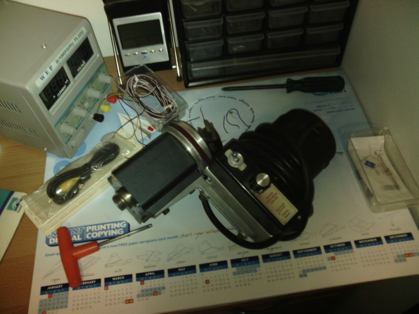
This is the assembly for the mill option on the converted lathe I had to throw away.
On the top you can see the the speed controller with a switch and a pot to vary the speed. This is the bit I really wanted to look at as it would be the part to simulate.
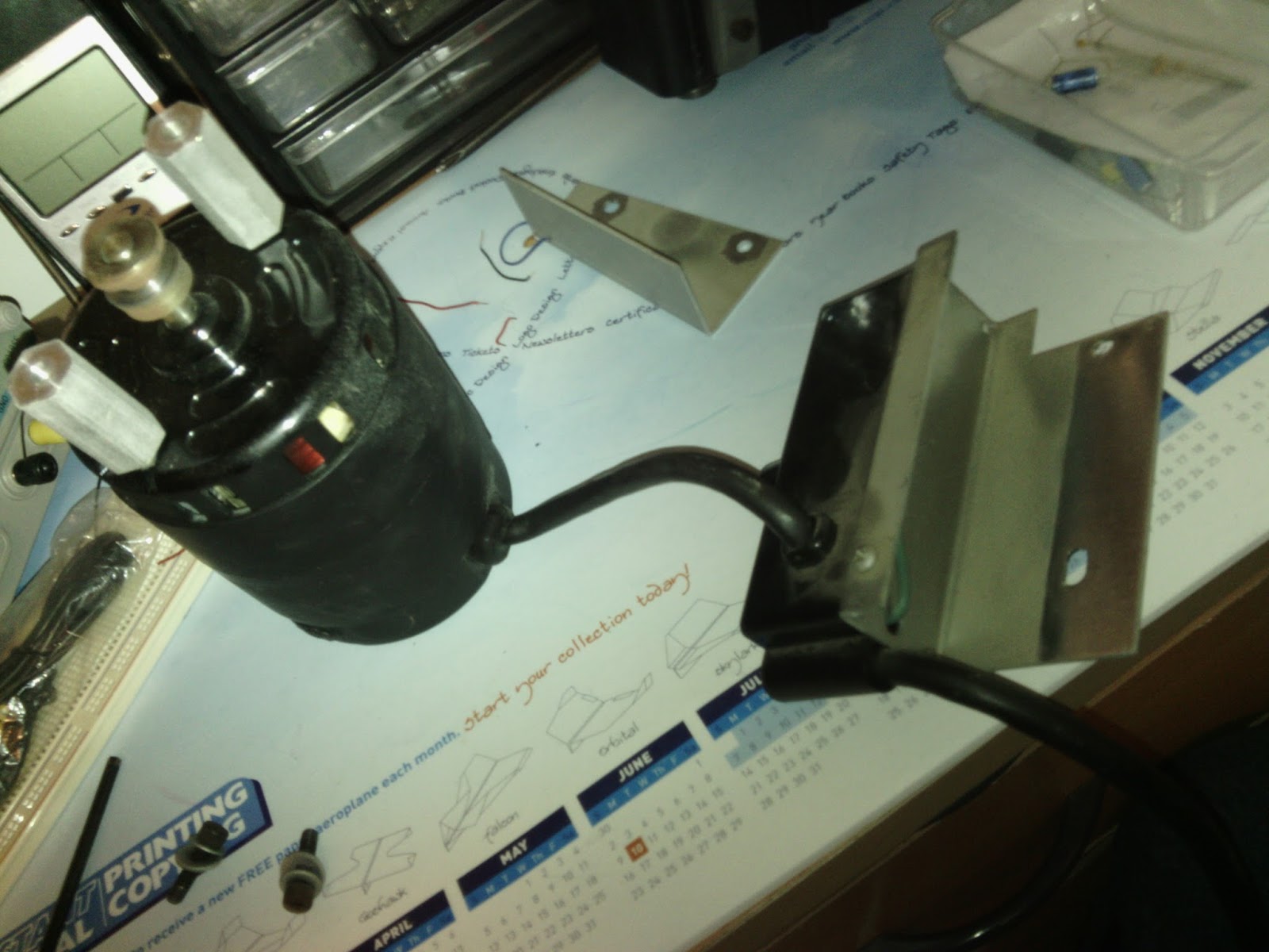
After I got a few screws undone it came apart fairly easily.
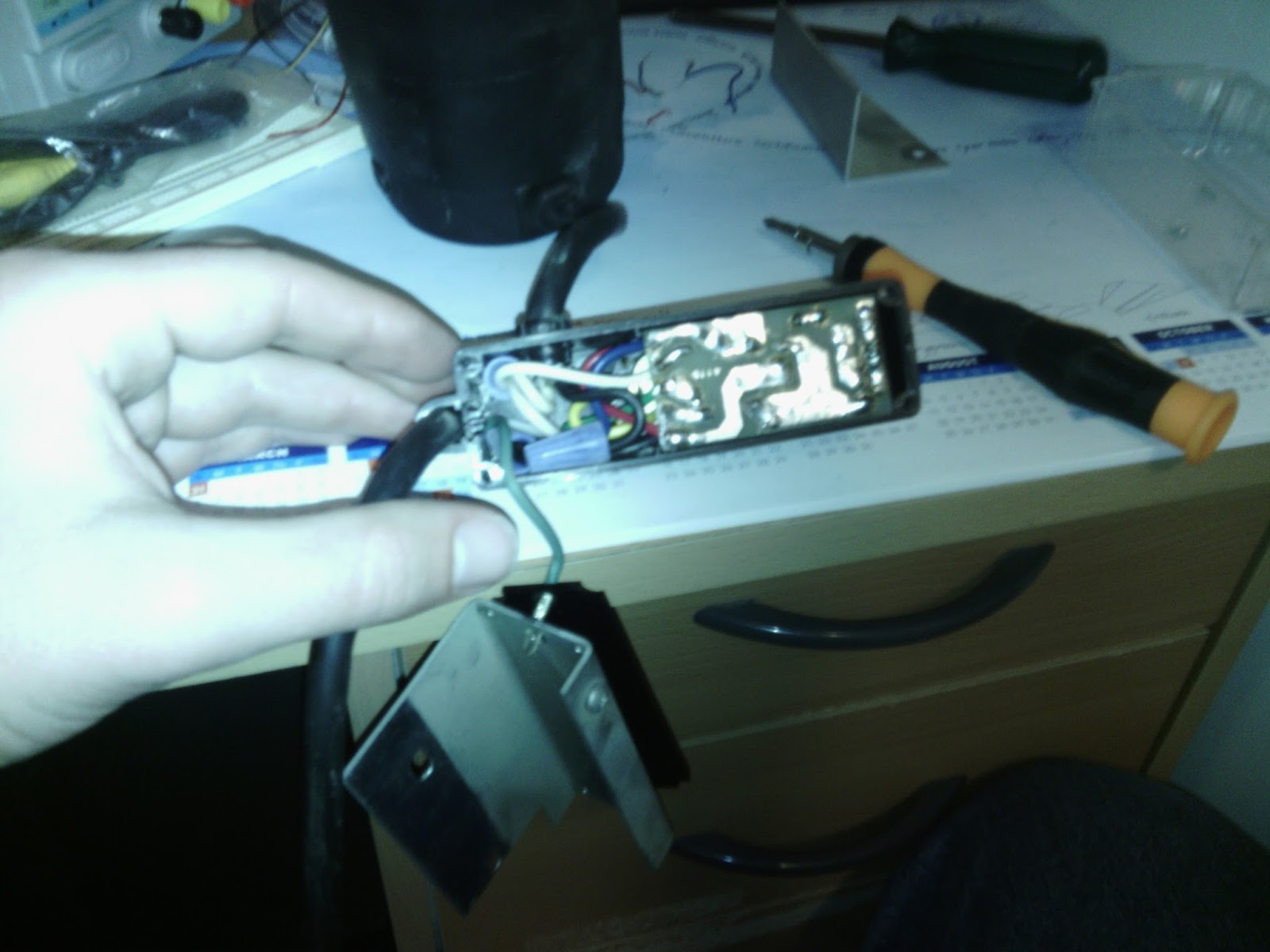
From there it was a fairly simple process to unscrew the ground cable and take the plastic backing off. From there I could see the conductor side of the PCB.
From there looking at the board it looked like there was a diode either as a reverse polarity protection or as a half wave rectifier. Working on the theory of it being a half wave setup I decided to hook it up to my power supply and see if it would turn or at least produce some kind of cogging effect. When I connected it up and slowly ramped up the supply voltage/current I was rewarded with rotation. Upon experimentation I found it to start spinning with about 0.55A and to just keep turning over at 0.50A.
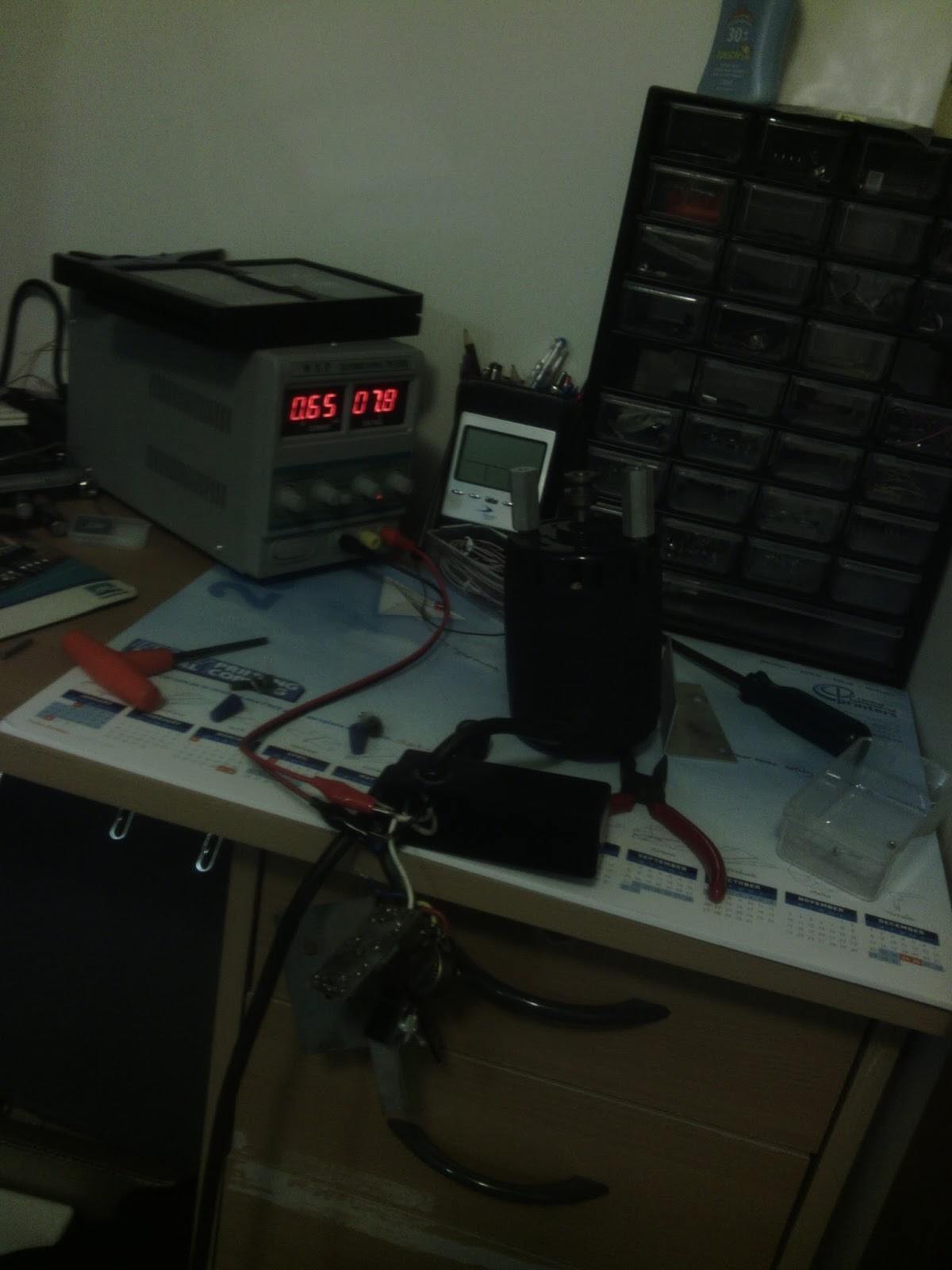
It's not very obvious but the motor is spinning slowly in this photo. I ramped the voltage all the way up to the maximum that the power supply will provide at about 29.7V which rewarded me with a nice whooshing noise from the air getting blown out of the motor. It looked like it was going pretty fast so I was glad there was a limit to stop me from going any further without having to bolt the thing down. Now I just need to confirm the voltage/current capacity of the PWM supply of the BeBoPr so I know if I need to build a buffer amplifier. The buffer should be able to be a fairly simple design with just a power transistor (probably some kind of FET) attached to a relatively small heatsink.
Being able to easily use these motors and spindles means that I can shave a fair bit of the potential cost of this project and I can focus on more important things like how to get the rotational speed of the spindle when it uses a plastic belt and a DC motor to drive it. I'm thinking some kind of back EMF based system. However the lighting conditions probably won't change too much so some kind of light based system could also be used. This is particularly true of the lathe which has all of the mechanism inside the headstock and is fairly well sealed to light.


Comments powered by CComment