

Reset counter
While Stop = False do
 Move state_of_ADC to register0
Move register0 to Permanent_Location[counter]
counter = counter +1 EndWhile
This would give a sampling rate that can be calculated fairly easily. The instructions are fairly basic so they should each only take 1 cycle to execute. Therefore 5 cycles are required to monitor the state. Therefore we just divide the clockspeed of the CPU by 5 to give us the sampling frequency(assuming CPU at 1GHz):
1GHz/5=200MHz
That's a 200MHz sampling rate. The only problem with this method is that the only real way to change the sample rate is to change the CPU's clock speed... But if I'm going to build a radio from scratch then I dare say I'll get used to adjusting frequencies with a voltage...The other program would be a GUI that allows the "settings" to be adjusted and a graph to be displayed. The "settings" would only effect the display. Unless I decide to implement software controllable attenuation or something useful like that. The attenuation would be done before the ADC and would be instructed to attenuate through the communication bus from the ADC which is activated for reverse transmission by sending a pin to say -5V which shouldn't happen in any other situation.
Anyway is anyone finds this helpful/instructive/wrong don't hesitate to leave a comment, more comments inspires me to write more :)
p.s. If anyone sees the HTML tags wrong or wants me to go through the tags I used here let me know any I'll put something up.
- Details
- Written by Rex ORegan-2
Attach the probe to PCB... heater turns on... remove it heater turns off... I can hear the relay ticking so that's not what caused it to overheat... some more research needed methinks... Wikipedia here I come...
- Details
- Written by Rex ORegan-2
Rather than just getting a high resistance to drop the voltage I realized that a higher current would also. By putting a resistor in parallel with the potentiometer I can increase the current flowing through the first resistor and use a smaller, more available resistor there to drop the same voltage.
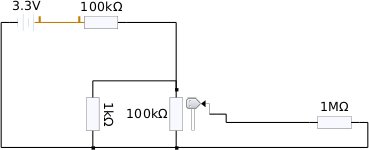
This is the schematic I did up in KTechLab to test my theory. the 1M resistor represents the smoke machine input. the max. voltage possible with this arrangement is about 30mV(50mV with a 5V supply). This means I should be able to supply the required 25mV for my max. temperature.
- Details
- Written by Rex ORegan-2
| Type | Temperature range °C (continuous) | Temperature range °C (short term) | Tolerance class one (°C) | Tolerance class two (°C) | IEC Color code | BS Color code | ANSI Color code |
|---|---|---|---|---|---|---|---|
| K | 0 to +1100 | −180 to +1300 | ±1.5 between −40 °C and 375 °C ±0.004×T between 375 °C and 1000 °C | ±2.5 between −40 °C and 333 °C ±0.0075×T between 333 °C and 1200 °C | |||
| J | 0 to +750 | −180 to +800 | ±1.5 between −40 °C and 375 °C ±0.004×T between 375 °C and 750 °C | ±2.5 between −40 °C and 333 °C ±0.0075×T between 333 °C and 750 °C | |||
| N | 0 to +1100 | −270 to +1300 | ±1.5 between −40 °C and 375 °C ±0.004×T between 375 °C and 1000 °C | ±2.5 between −40 °C and 333 °C ±0.0075×T between 333 °C and 1200 °C | |||
| R | 0 to +1600 | −50 to +1700 | ±1.0 between 0 °C and 1100 °C ±[1 + 0.003×(T − 1100)] between 1100 °C and 1600 °C | ±1.5 between 0 °C and 600 °C ±0.0025×T between 600 °C and 1600 °C | Not defined. | ||
| S | 0 to 1600 | −50 to +1750 | ±1.0 between 0 °C and 1100 °C ±[1 + 0.003×(T − 1100)] between 1100 °C and 1600 °C | ±1.5 between 0 °C and 600 °C ±0.0025×T between 600 °C and 1600 °C | Not defined. | ||
| B | +200 to +1700 | 0 to +1820 | Not Available | ±0.0025×T between 600 °C and 1700 °C | No standard use copper wire | No standard use copper wire | Not defined. |
| T | −185 to +300 | −250 to +400 | ±0.5 between −40 °C and 125 °C ±0.004×T between 125 °C and 350 °C | ±1.0 between −40 °C and 133 °C ±0.0075×T between 133 °C and 350 °C | |||
| E | 0 to +800 | −40 to +900 | ±1.5 between −40 °C and 375 °C ±0.004×T between 375 °C and 800 °C | ±2.5 between −40 °C and 333 °C ±0.0075×T between 333 °C and 900 °C | |||
| Chromel/AuFe | −272 to +300 | n/a | Reproducibility 0.2% of the voltage; each sensor needs individual calibration. |
Page 43 of 46 Older PostsPopular TagsMost Read PostsVisitor Info
Who Is Online2
Online
2024-05-14
| |||
