

I=V/R
I=V/infinity
I=0
This is why an op-amp has a high input impedance.
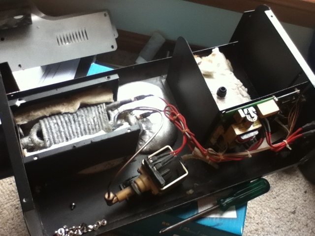
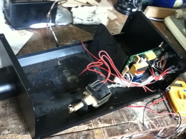
The temperature probe connections have a resistance of around 1000k. That's pretty high, which when coupled with the polarity markings indicates that there is an op-amp on the board and the temperature probe is a low current voltage source. Also known as a thermocouple.
This means I can now simulate the presence of the temperature probe by supplying an appropriate voltage(not sure how big yet though). By simulating the presence of the thermocouple I can test if the electronics will turn off the heater current at some point which means that it was just the thermocouple that failed. The outer braid of the thermocouple has failed where it enters the remains of the aluminium so that makes me think that something went badly wrong with the thermocouple.
While I had the multimeter out I also measured the heater coil's resistance- this came out at about 700k. So with a little math we can calculate the current flowing through the coil and also the wattage(not really that important but might be interesting to see how much power the electronics use).
I=V/R
I=230/700k (Pretty sure 230V isn't RMS but I know it isn't Peak to Peak so it shouldn't give us a number that is too high)
I=230/700 000 (Now in SI units)
I=0.003288571A (Seems very very low ???)
Now for power consumption:
P=IV
P=230*0.003288571
P=0.76W
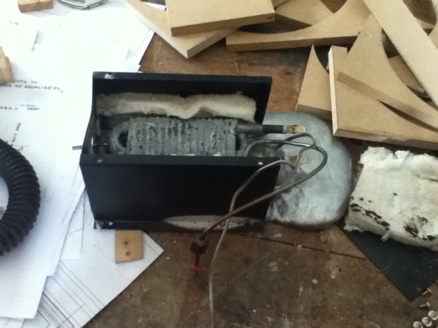
This is clearly wrong so I decided to check again... It turns out that my fingers have a resistance of around 700k ohms and it was this resistance I measured. The heating coil appears as an open circuit so I think I'm going to have to melt out the remains of the Aluminium block and get a closer look.
- Details
- Written by Rex ORegan-2
User Rating: 5 / 5

So I am going to try and repair it as the only problem seems to be with the heat exchanger(Al structure fully melted and in a puddle in the bottom of the case) and somewhere in either a relay that controls the heating element or the temperature probe. My gut feeling is that the temperature probe is to blame and hopefully I can find a way to test it(perhaps with the oxy-acetylene torch from school). When checked with a multimeter the temperature probe gave a reading of between 0 and 3 ohms at room temp (about 30 degrees C) and a voltage reading of 0V(2000mV scale). If it were a thermistor I would expect the resistance to be somewhat higher and if it were a thermocouple I would expect a higher voltage(from a little reading on Wikipedia).
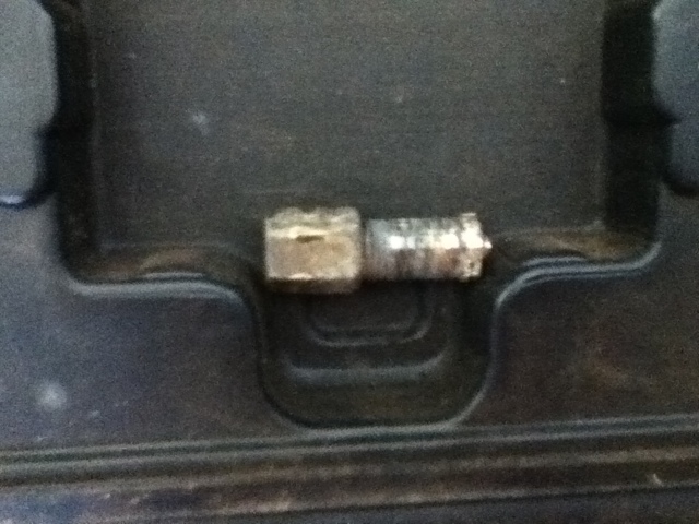
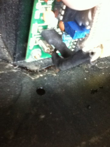
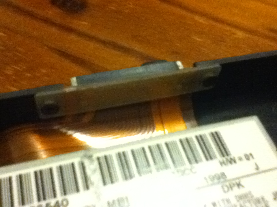
Just a quick picture to remind me which way to connect the temperature probe. It appears to be polarised which makes me think it's a thermocouple. If it is a thermocouple and a wire has broken from repeated heating/cooling cycles then that may explain the lack of voltage and the lack of voltage would explain the amount of heat applied to the heat exchanger when it overheated.
- Details
- Written by Rex ORegan-2
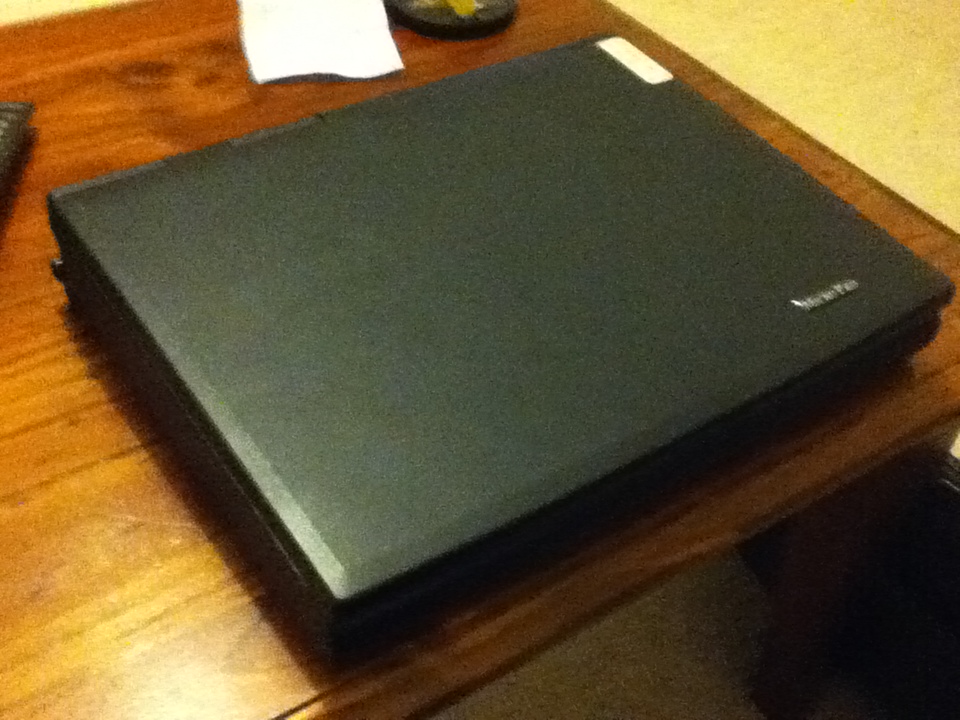
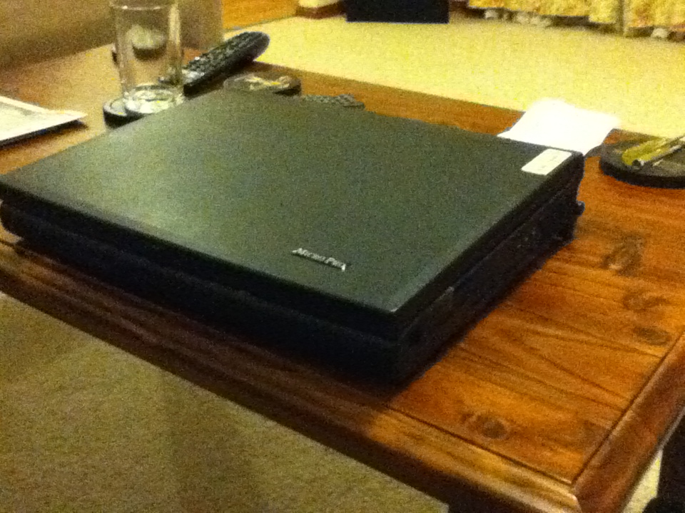
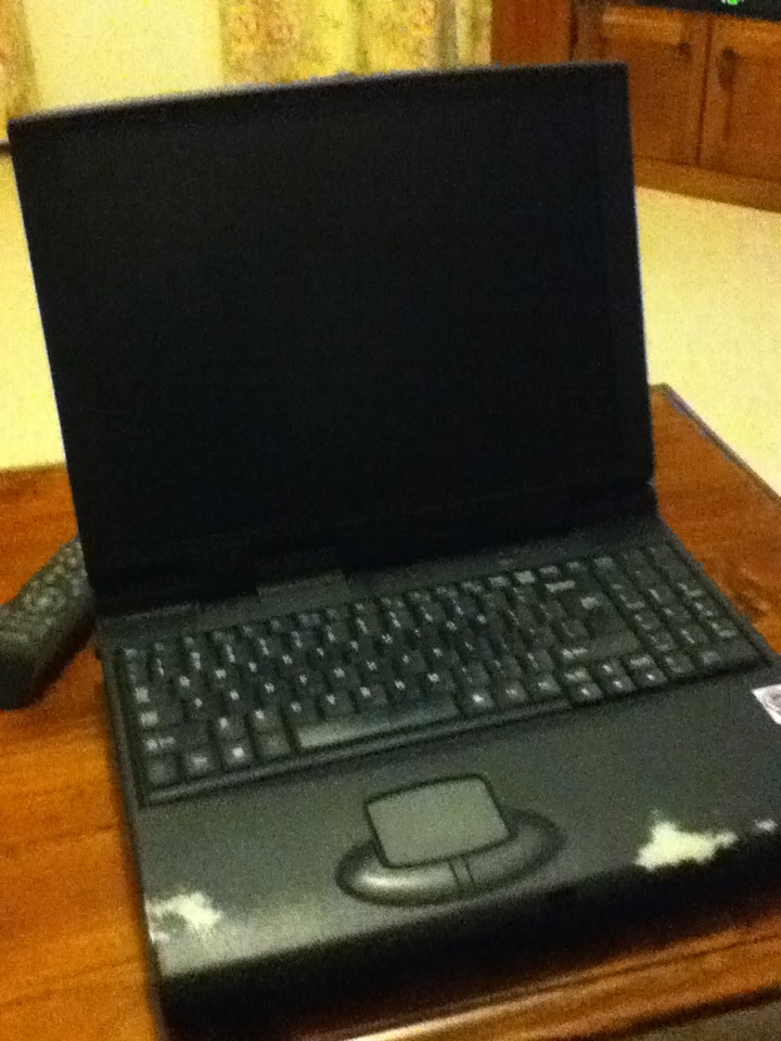
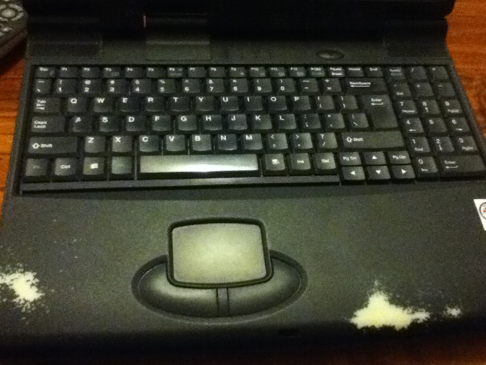
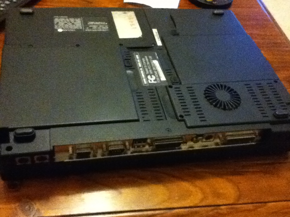
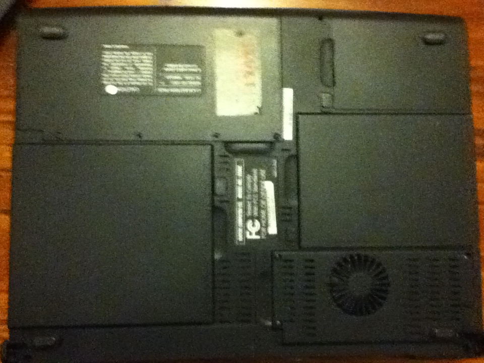
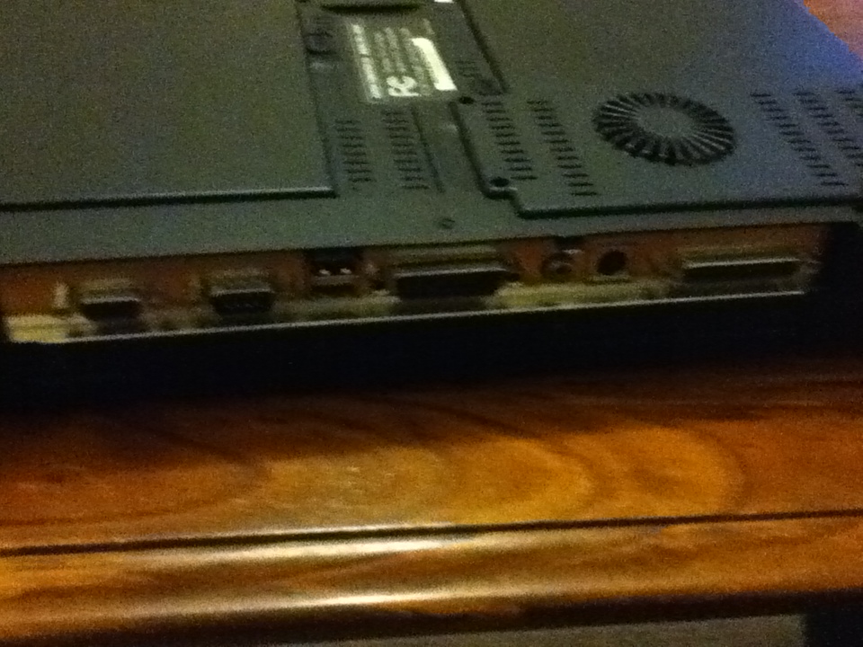
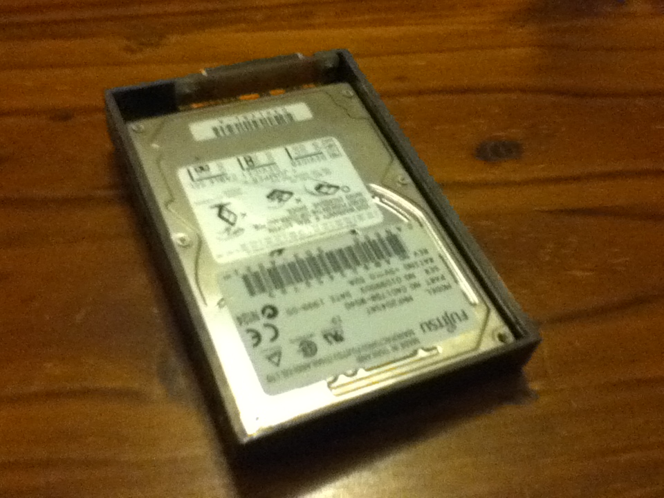
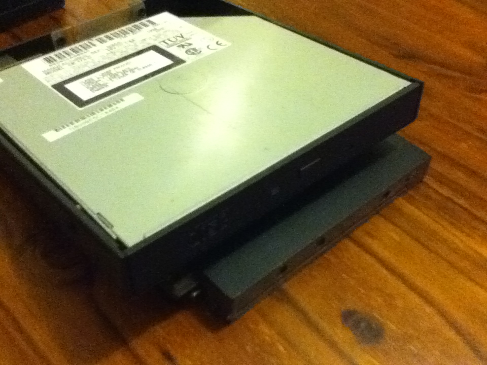
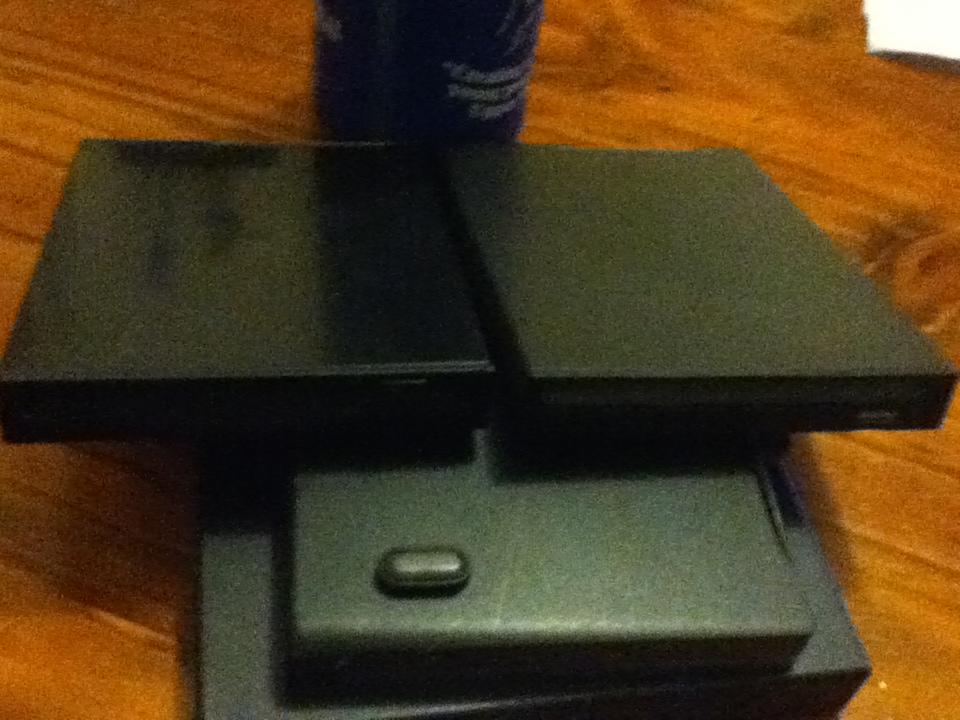
Some views of the bottom. At bottom with all of the removable sections partly removed. Clockwise from top right there is the CDROM drive, HDD bay, Floppy/Zip drive bay.
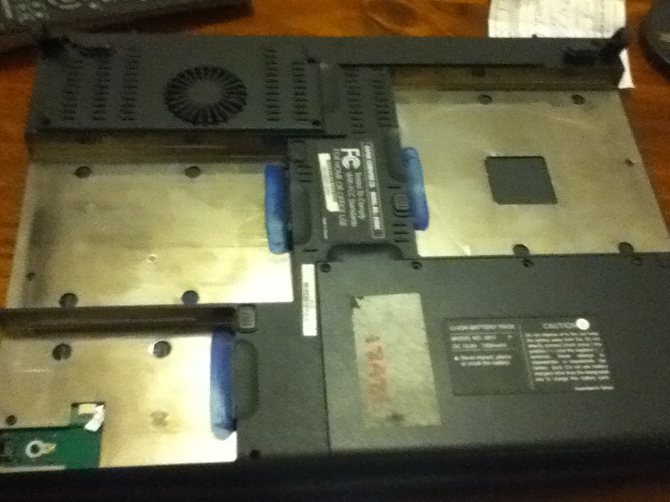
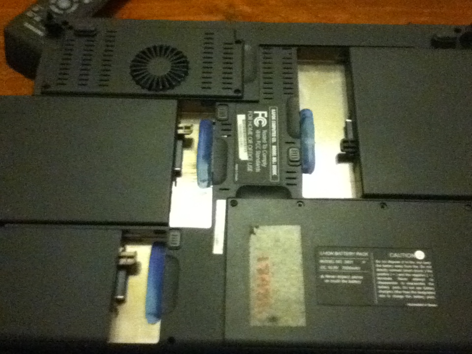
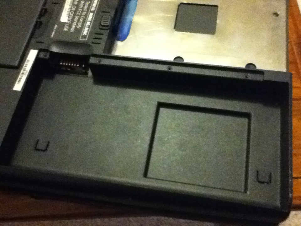
Here all of the removable modules are removed. Bottom left we can see the modem module with broken ribbon cable from a previous teardown I did.
If you want any more detailed pictures or info post a comment and I'll get some for you.
- Details
- Written by Rex ORegan-2
So I'm not happy with the stock electronics for the Nerf Stampeed. Using a 7 shot clip you can easily fire away all of your darts and still not hit anything. Also the 6 D cell batteries are a pain to replace and are massively heavy.
The solution:
Put a small microcontroller such as an Amtel AtTiny of some description, replace the current power switch with a 3-way switch to allow selecting between:
-Full Auto(Stock Setting)
-Burst(fires 2 or 3 darts at a time)
-Semi-Auto(fires 1 shot but automatically re-cocks)
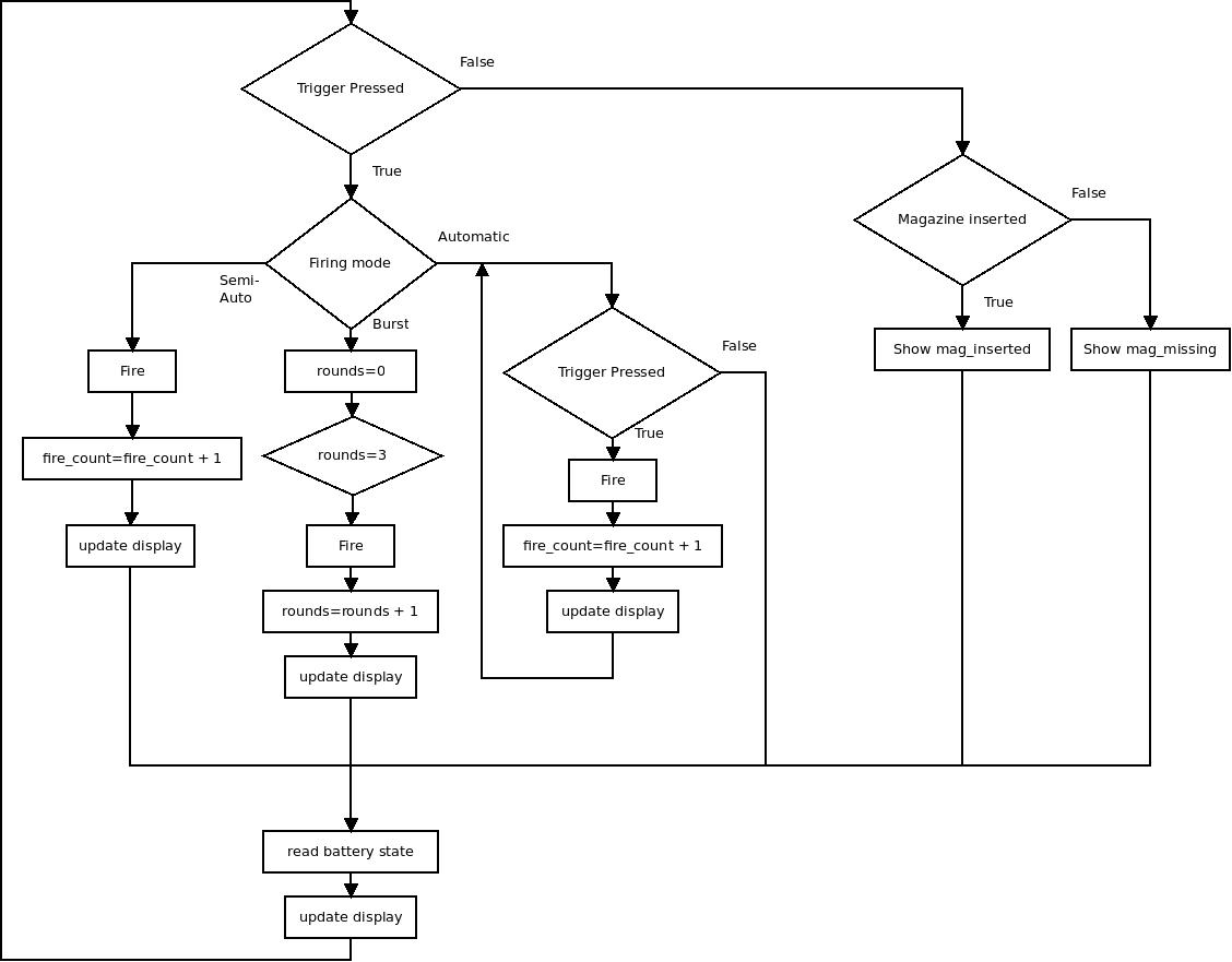
Some way of displaying the number of rounds fired in battle and the battery level should be easy to set up. If I can find a way to differentiate between different magazines then a readout showing how many are left in the mag. would also be useful.
A display like this only needs an SPI interface, everything else can be controlled with digital I/O except for reading the battery state, the best solution for which I don't quite know right now but will probably need an ADC channel.
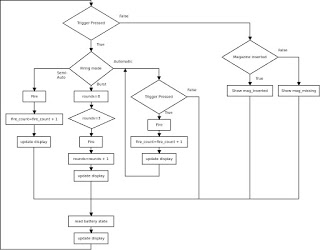 This is a fairly quick flowchart I did up showing the basic functions that will be called and when... not quite up to drawing a flowchart to show exactly how each function works... but I figure this is a start.
If you want to know why I did up a flowchart for this just ask me to put up the Qt code and flowchart that I taught myself and wrote in 1 week or so... the flowchart was about 2.5m high when printed so small it was barely readable... Originally I was trying to work it all out in my head... doesn't work that way... not like the simple little things they wanted me to do flowcharts for in my sfotware design and development course...
If you want to know why I did up a flowchart for this just ask me to put up the Qt code and flowchart that I taught myself and wrote in 1 week or so... the flowchart was about 2.5m high when printed so small it was barely readable... Originally I was trying to work it all out in my head... doesn't work that way... not like the simple little things they wanted me to do flowcharts for in my sfotware design and development course...
- Details
- Written by Rex ORegan-2
Page 44 of 46
