Just a quick update on how the mill is going as that's the only thing that's actually had anything done on it recently. I finally got the software issues sorted and worked out a display, then when I pressed the go button to power on the motors they hissed like they should for a fraction of a second. Then.. all of the power died to the board.
A second test confirmed that this is consistent behavior unfortunately. I think what is happening is that the turn on current draw of the steppers is too high for the computer PSU and it trips the overload protection. To test this what I'm going to do is connect my bench power supply in parallel with the computer supply and then after starting the motors wind down the current. That should tell me if the computer PSU will handle the base load current.
If it will then I will probably put some kind of large capacitor across the 12V rail and GND to help minimize the surge. I may do a quick writeup on the display arrangement I finally got working, particularly if there is some interest there.
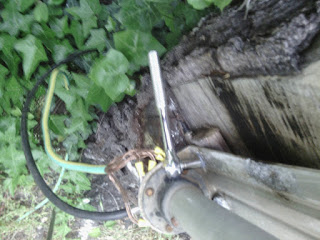
All week I've been trying to work out what this is supposed to do all week. It came from the base of the my vertical HF Antenna. It's some kind of inductor that has one end connected to the shield and the other end connected to the actual antenna. The centre of the coax is connected to the same point on the antenna through the middle of the inductor. To see me dis-assemble the antenna or if you have any suggestions keep reading past the break.
First thing to do was to get the big metal stick down. The thunder had just rolled away so I figured it would be safe enough.
No proper tools here. No point going to the shop just to get a tek bit. An 8mm socket works fine.
I finally got organised with a table out the back so I actually have space to work on a project like this.
Not usually a good start to dis-assembling something when I need to use pliers on knurled parts.
Turns out only one screw was holding the base of the pole onto the bracket. With that removed and a little twisting it all came off. So far so good.
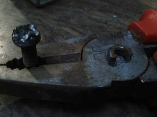
Hmm. This one not so good. This bolt was a little bit burred and there was no way I was going to hold the the bolt still. So I tried to drill it out. Unfortunately the only drill bit I could find was a little too small for the bolt and only mangled the head of it. For my next trick I drilled out the nut instead. While not the conventional method as you can see it did work.
And this is where I started to get confused. But this is a trapped antenna so maybe there is a good reason for it.
But this is where I completely lost the plot. This inductor will be acting a bit like a transformer but I don't know if it would be making a significant difference. Being an inductor it's reactance(?) goes up with frequency. That means that possibly at the frequencies we are looking at it will look like an open circuit. But then maybe it could appear as a reactance which would produce some kind of voltage divider action.
Most of that's probably wrong. It's time to stop guessing and find out. Over the weekend I'll probably run some simulations or something and see how it would behave under various situations and I'll see if I can make up some useful graphs.
If you have any idea why my antenna has a coil in it's base it'd be great to hear from you.
So this afternoon I finally thought to check on why my HF radio isn't working very well. I finally had the great idea to check the resistance between the actual antenna and the bracket that holds it's base. This bracket is what I've connected all of my earth wires to and should be separate to the rest of the antenna.
Guess what...
It aint... Looks like the reason I've been having such poor reception is because the antenna is actually being held to ground. So it turns out that any reception has actually been the result of a bad thing. Keeping positive though. I am going to say it's something to do with the impedance at RF being not = to 0 ohms.
So over the course of the week keep an eye out for how I fix this problem with too much grounding as opposed to my original theory of not enough.
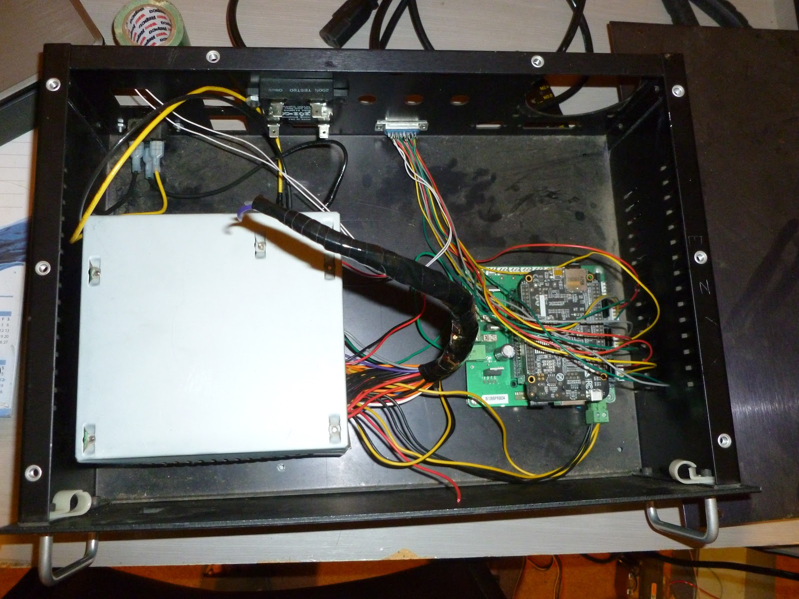
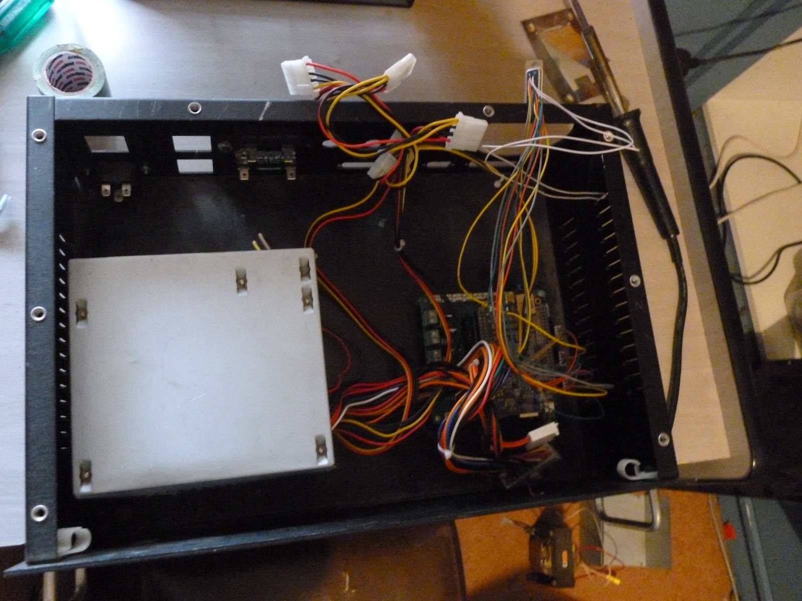
I've finally got more work done on the Mill. I was hoping to get a shot of the control box powered up with the laptop running the control software next to it for the cover photo. However it seems that I need to keep playing with the software a little longer.
Instead you get a photo of the finished product as it stands. I know the wiring isn't the neatest or prettiest. But you can take my word for it that it does work now. Follow on after the break to see how I got to this point. I was cleaning up the other day and I discovered an old ATX computer power supply that I was confident still worked. The only issue was that the IEC connector for the power cord in the back was mangled so there was no testing without opening it up and hooking some wires up.
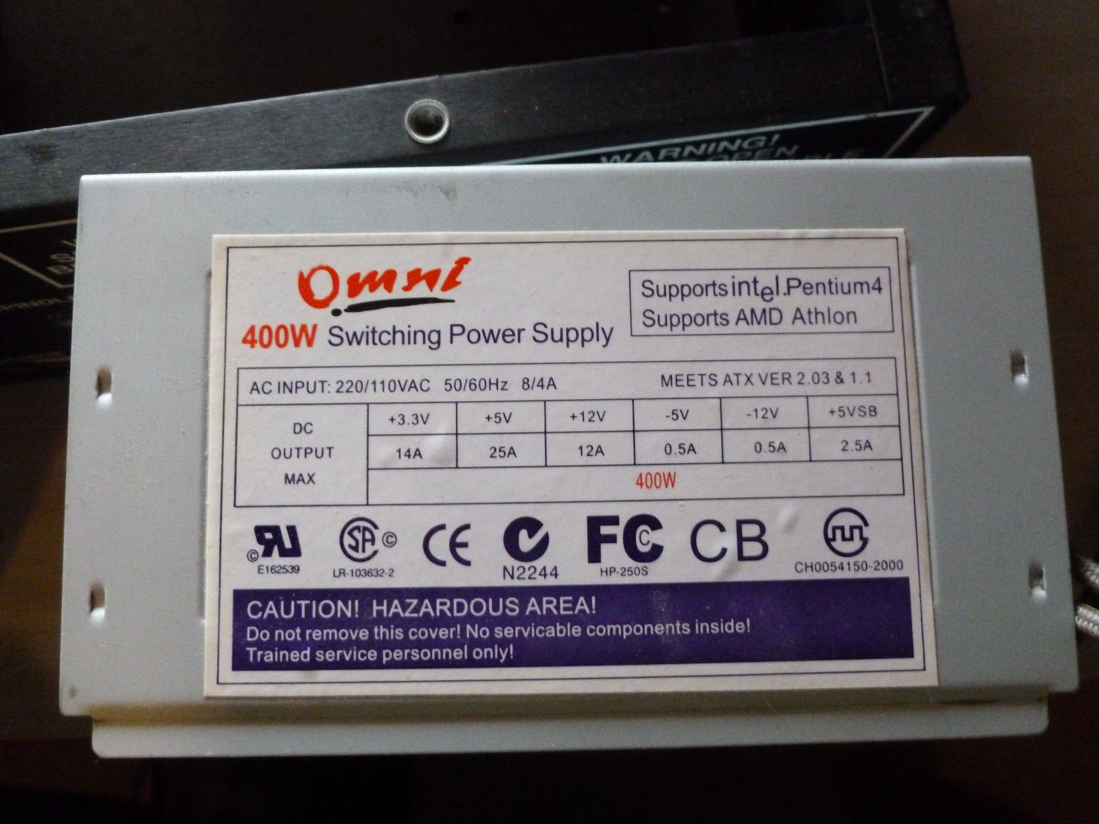
The specs from the computer power supply I am using. that +12V rail should have enough oomph.
Thankfully the original case for the control box had an IEC connector in the back of it and the connector for 110V and 240V is the same. This means that all I need to do is get some wires to connect it to the power in on the circuit board for the re-purposed power supply.
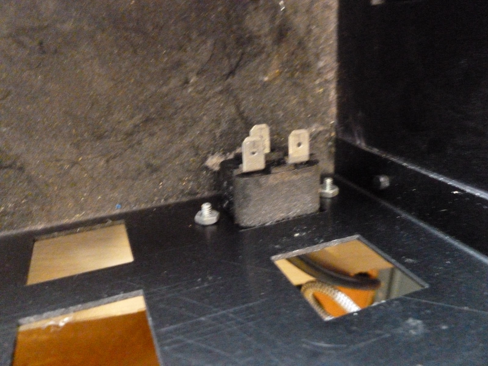
The inside of the IEC connector.
The connector even had spades on it so all I needed to do was splice in some wires from the original wiring harness onto the ends of the wires that I cut free from the bad IEC connector on the new power supply.
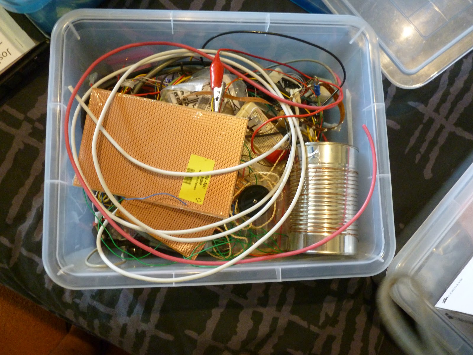
To get these spade connectors that I needed to splice in I found in my electronics box a cable with 2 mains wires heat shrinked inside and another loose wire for the earth.
The pit of dispair.
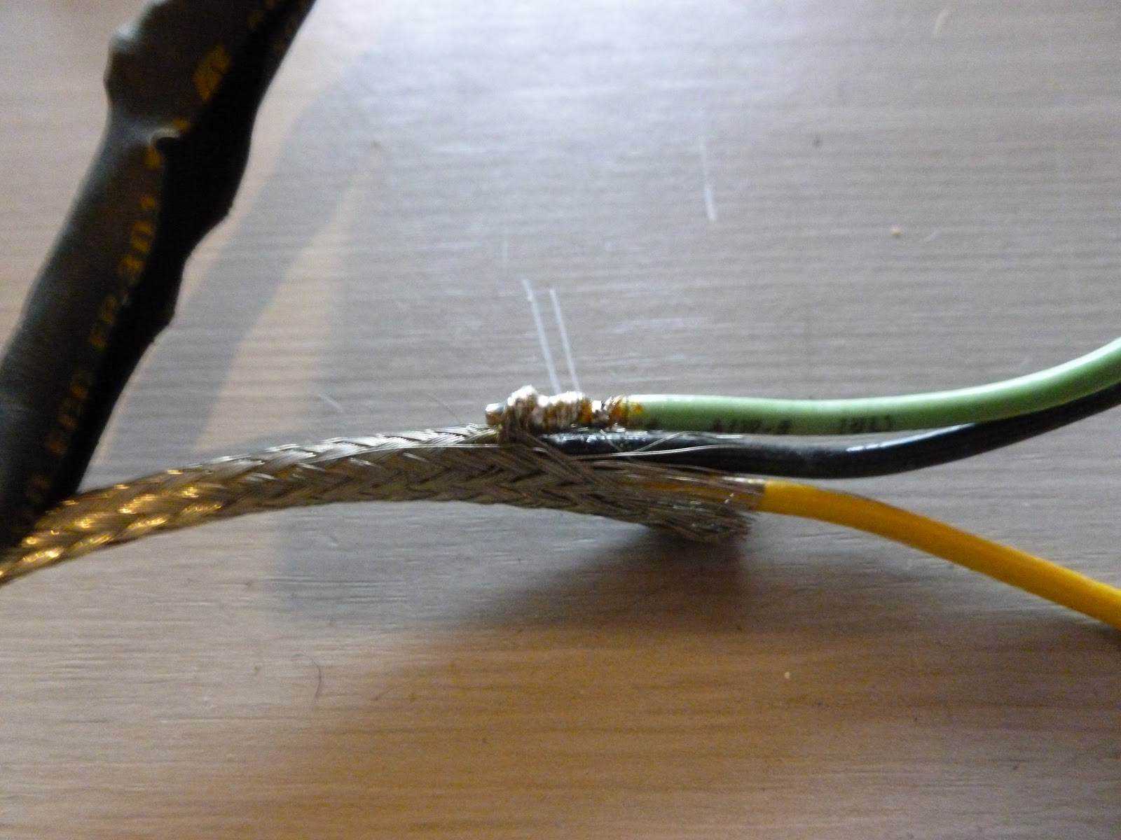
This is what the cable looked like before I started with it.
I cut back the heatshrink from the outside and discovered that the earth wire that leads out of the bundle is actually connected to a shield. There seems to be a lot of them in the multicore bundles on this machine. I wonder if they were worried about noise?
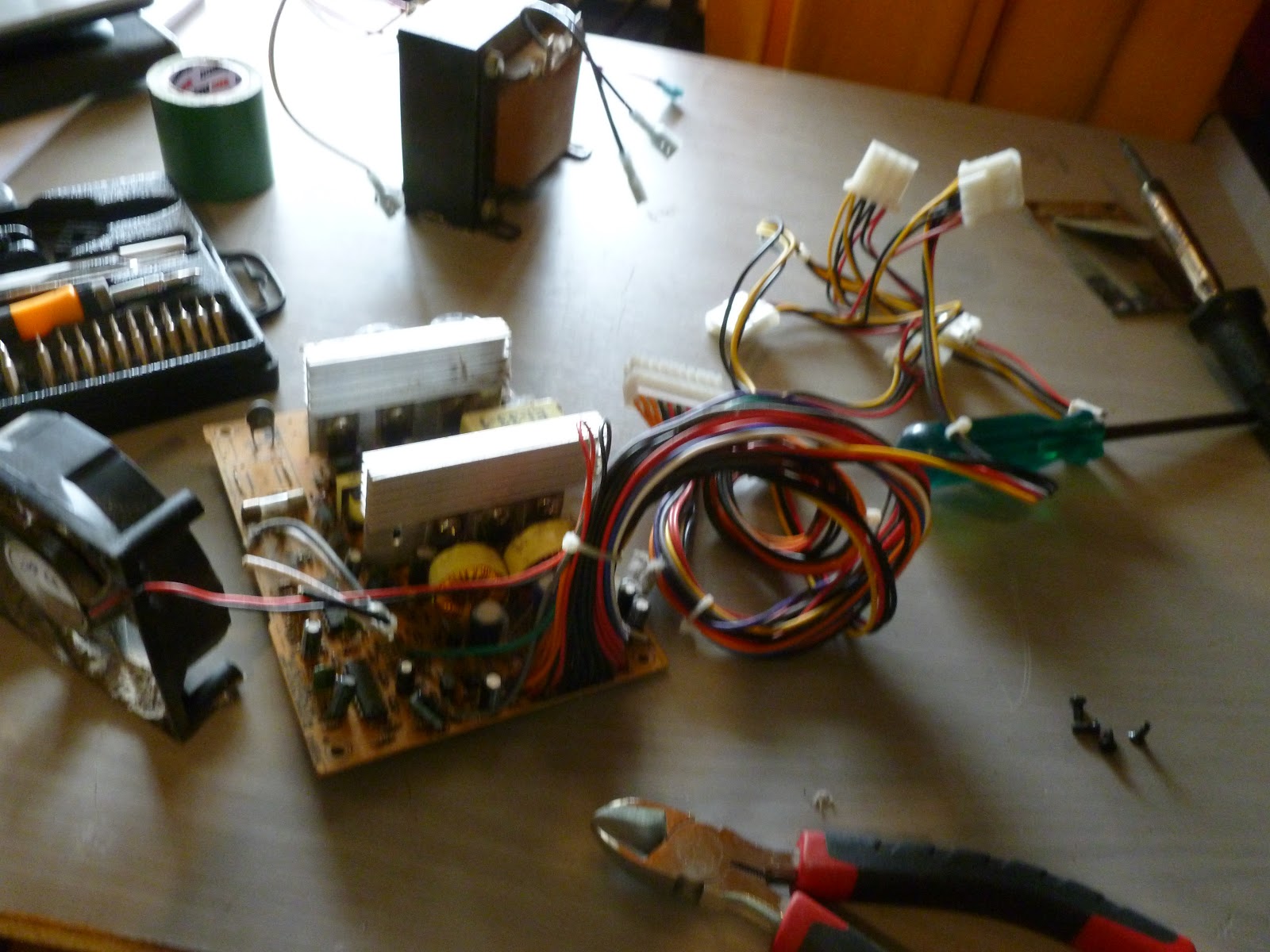
I quickly pulled the power suppy apart to get a quick look and inspection to make sure everything is as it should be, which it is.
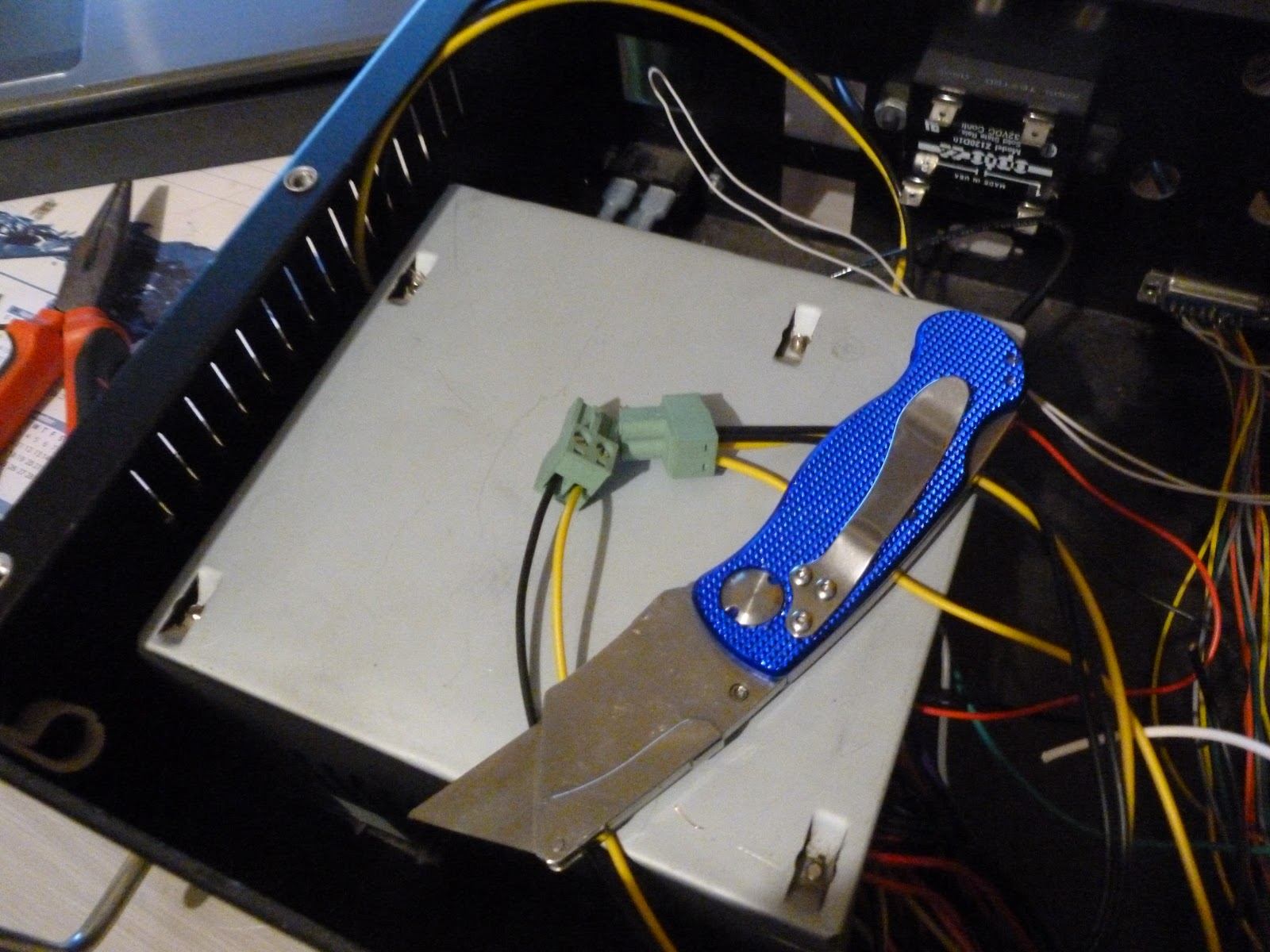
To mount it I just put a few more holes in the bottom of the case and used the existing holes that are threaded into the top of the supply to mount it upside down in the case. This gives me a good solid mounting and also means that it's a little safer if I any of the capacitors on the supply remain charged after removing the power. With the grounded metal case facing up like that you'd have to reach under it to touch high voltage live wires.
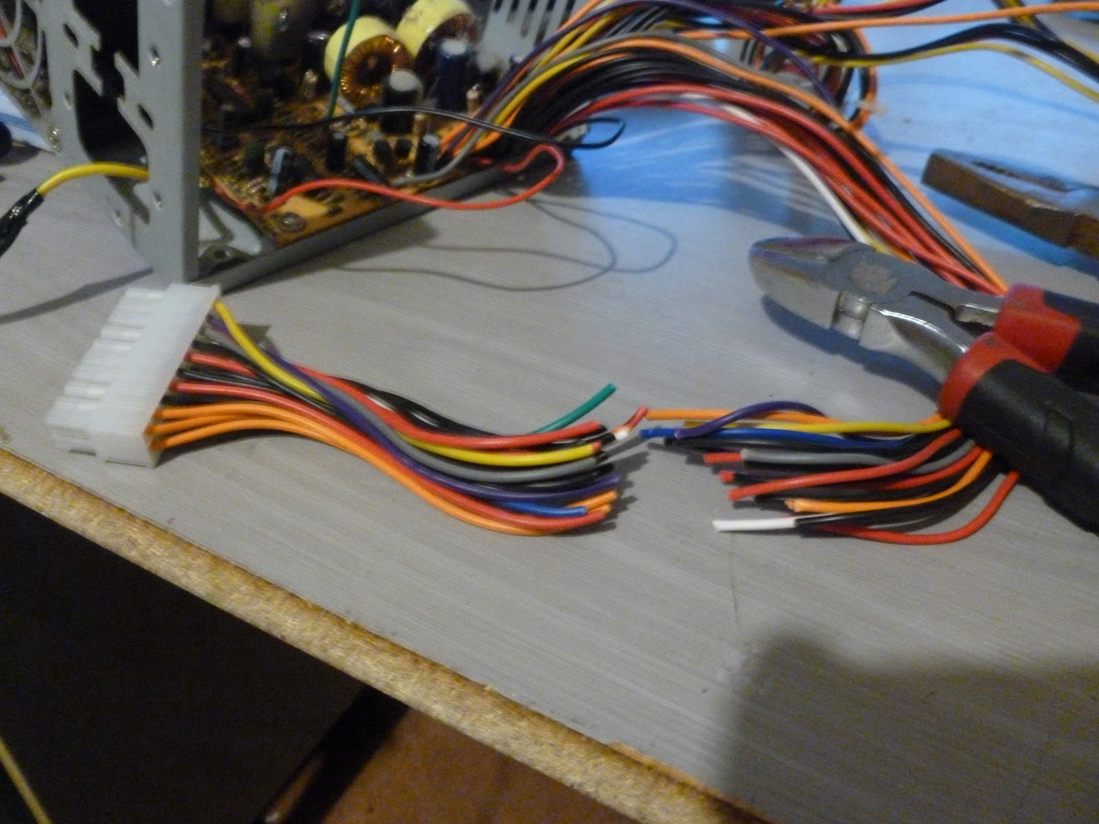
At this point it was just a case of splicing in the new mains power connector and cutting away any unneeded wires, then hooking them up to the control circuit board.
Chop it!
These 2 plugs are wired up to the +12V rail and GND. They plug straight into the control board.
Once this was done all that was left was to wrap up all of the unneeded wires neatly so if I do need a +5V rail at some point I can get it easily.
From here I put the lid on and tested it. Everything worked as advertised. Now all that's left to make work is the spindle needs power and possibly a speed readout depending on how fancy I feel and a little fiddling with the software stuff to make it actually controllable.